Technical Specifications
500+
Distributed Design Capacity
0deadlocks
ETA-Based Pre-Elimination
24/7
Non-Stop Operation
Key Features
7 featuresETA-Based Deadlock Pre-Elimination
Predicts collision probability via ETA before robots reach intersections and pre-coordinates routes. Intersection waiting is structurally eliminated.
Learn more ↓Industrial MAPF Engine
Time-space simultaneous path search reflecting robot geometry, kinematics, and dynamic obstacles. Academic CBS algorithm adapted for industrial use.
Learn more ↓Multi-Map Fleet Control
Robots can follow routes across maps in a multi-map environment, with the maps connected to one another through Portal nodes. When a robot passes through a Portal node, Map Change and Position Calibration actions run automatically, so position alignment and map switching happen at the same time.
Learn more ↓Smart Integrated Management of Field Equipment and Upper-Level System Integration
Easy integration with upper-level systems and field equipment
Learn more ↓Linear-Scaling Distributed Architecture
Zone-based distributed ACS with Handover protocol ensures linear performance scaling as robot count increases.
Learn more ↓Pre-Deployment Simulator
Fully validate scenarios before deployment with Core-Sim, PLC-Sim, and accelerated simulation. Structurally reduces on-site risk.
Learn more ↓Redundancy + Auto Recovery
Active-Standby server redundancy and auto recovery ensure continued control even during server failure. Eliminates single point of failure.
Learn more ↓ETA Predictive Traffic Management: No Stopping at Intersections
Navi-Brain's traffic management operates on 'when will the robot arrive where' rather than 'where is the robot now'. ETA is calculated reflecting each robot's actual speed and acceleration. Confirmed routes are assigned only up to deadlock-free zones. After the leading robot passes, reserved routes are automatically confirmed so following robots can drive continuously without stopping.
- ETA-based deadlock pre-elimination — no intersection waiting
- Non-stop guided route assignment with VDA 5050 Base/Horizon
- 500+ robot linear scaling with zone-based distributed ACS
The paths of the two robots meet at node N-00. An intersection is a shared resource that only one robot can occupy at a time, and this single point is what traffic management actually has to solve.
Many robots work in the warehouse at the same time. Each one has a current position and a destination. The dashed lines show each robot’s goal.
MAPF
Multi-Map Fleet Control
Robots can follow routes across maps in a multi-map environment, with the maps connected to one another through Portal nodes. When a robot passes through a Portal node, Map Change and Position Calibration actions run automatically, so position alignment and map switching happen at the same time.
The elevator is on the left and the per-floor maps are on the right. The 1F, 2F and 3F maps sit at the height of their own floors, and each is a separate map with its own origin and version. The robot uses only one floor map at a time.
A site is divided by floor, and also into zones within the same floor. 1F west and east, 2F west and east, and all of 3F: each of the five zones is an independent map. Robots move only within their own zone, but all five maps are managed in one place, Navi-Brain.
Smart Integrated Management of Field Equipment and Upper-Level System Integration
Navi-Brain connects automatic doors, elevators, hoists and chargers through a gateway each, and registers every device on the node-link map. Upstream, it integrates with host systems such as WMS, MES and MCS to receive work orders; downstream, it connects directly to the robots. Robots never talk to devices; they only request passage permission from Navi-Brain, so when a device is replaced the only thing that changes is one gateway.
Supports seamless integration with upper-level systems such as WMS, MES, and MCS, while letting you easily configure a wide range of field devices — chargers, gates, hoists, and more — by mapping each one 1:1 to a node.
- Toggle buttons in the UI make it easy to switch equipment On/Off and manage field equipment availability in real time.
- When equipment is deactivated, unnecessary control commands are blocked at the source, improving system stability.
- Sends standardized messages over standard protocols such as VDA5050 and OPC-UA.
Heterogeneous AMR Control via Standard Protocols
VDA5050 is a communication standard between AGVs/AMRs and higher-level control systems, established by Germany's VDA and VDMA. As an open, MQTT-based interface, it standardizes driving commands (Order), status (State), and instant commands (InstantAction), so robots from different manufacturers can be controlled the same way from a single fleet management system.
- Operates AMRs/AGVs/AFLs from different manufacturers and models simultaneously on a single ACS, eliminating vendor lock-in
- Standardized JSON messages such as Order / State / InstantAction / Factsheet eliminate the need for robot-specific integration development
- MQTT-based real-time communication — a lightweight Pub/Sub architecture delivers low-latency status collection and command delivery even across large robot fleets
- Connects to upper-level systems such as WMS, MES, and ERP through standard interfaces, forming a single workflow from order to transport completion
Full Pre-Deployment Validation with Simulator
Core-Sim allows pre-validation of driving scenarios using actual field maps and robot parameters. PLC-Sim tests facility integration scenarios in advance. Accelerated simulation verifies days of operation patterns within hours, structurally reducing deployment risk.
- Core-Sim: scenario validation based on actual map and robot parameters
- PLC-Sim: advance validation of facility integration scenarios
- Accelerated simulation for early identification of long-term operation patterns
- Multi-user simultaneous map editing support
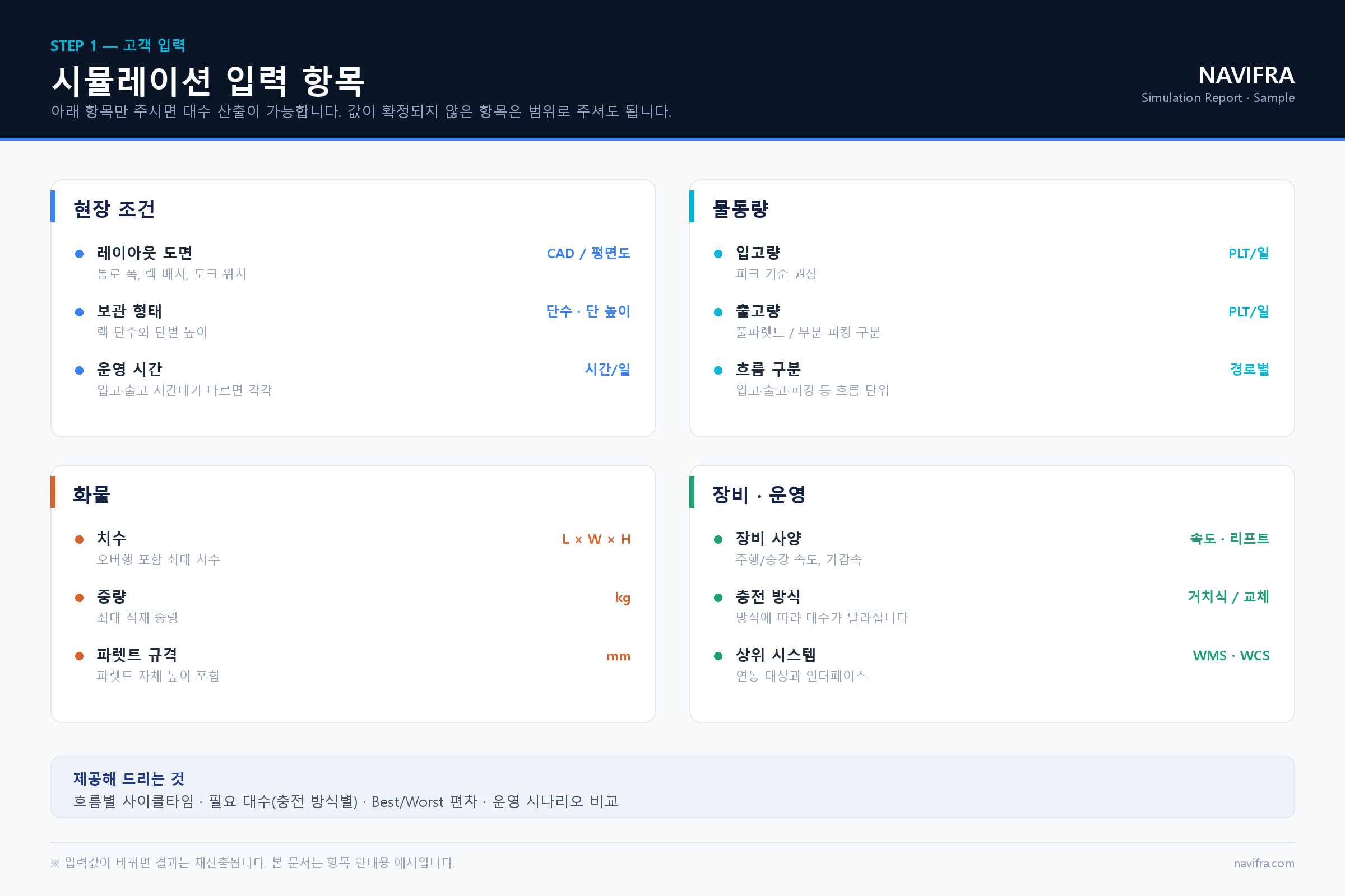
① Customer Inputs
We receive the site layout, storage type, throughput, cargo specifications, and equipment and operating conditions. Items whose values are not yet finalized can be provided as ranges.
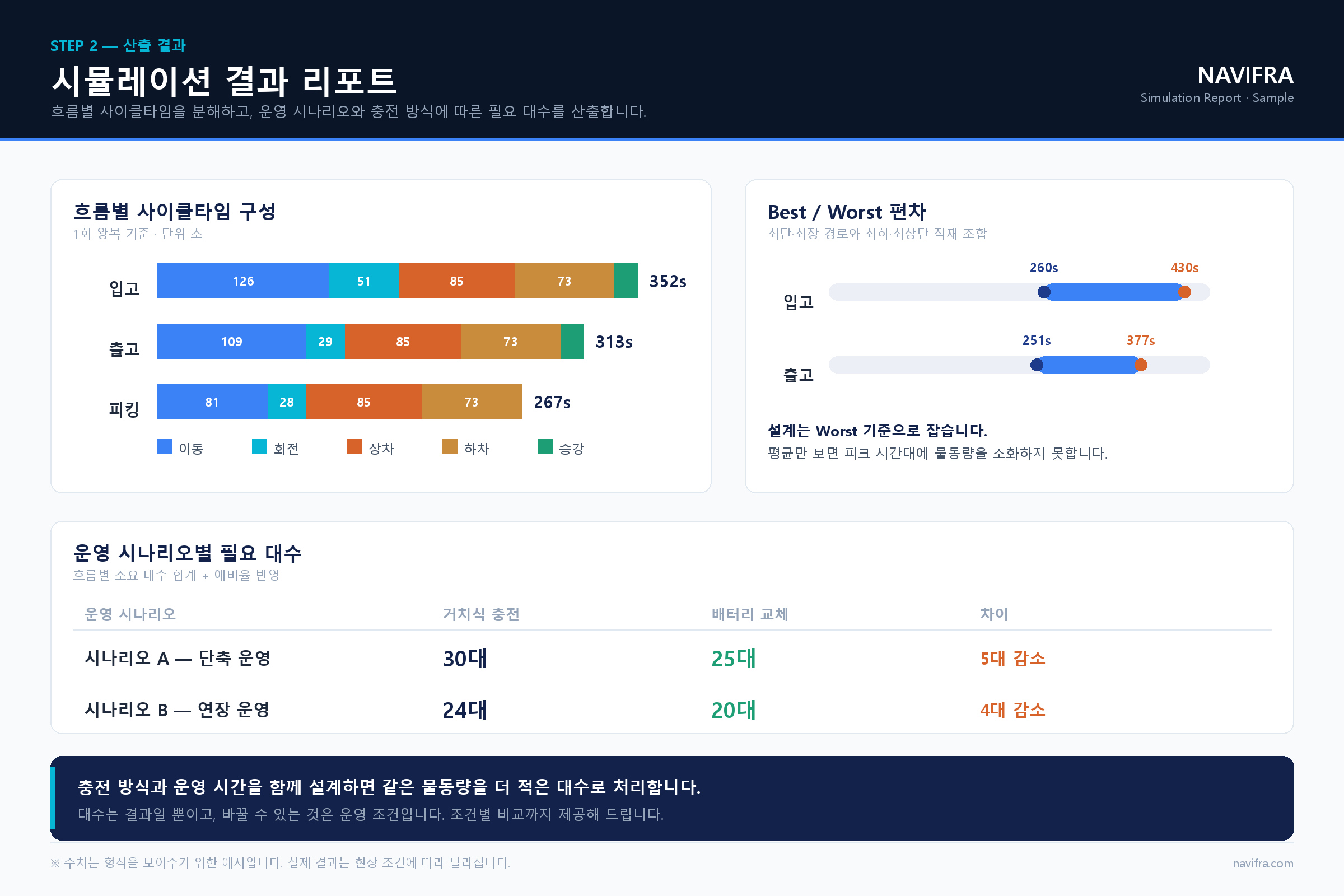
② Simulation Results Report
Breaks down the cycle time of each flow step by step and presents the required number of units by operating scenario and charging method, along with Best/Worst variance.
Contact Sales about Navi-Brain
Analyze your site with our experts and design the right solution. We support you through every step, from consultation to on-site installation.